I completed 98% of the wiring project this last weekend. The only remaining task is to replace the structural beams below the battery box for the starting 8Ds, replace the box and make permanent the power feeds to the new distribution panel. This project consumed over 300 ft of wire ranging from 18 gauge to 2/0. Don’t even ask the cost. But the satisfaction of having completely new power wiring from the engine room to the pilot house electrical panel is rewarding and the piece of mind once we are underway will be invaluable.
Someone must have been watching over me through this project. I only electrocuted myself once while tightening the power feed from the starting batteries. And best yet – both engines fired within seconds after sitting idle since our arrival at Ortega in October of 2001.
This is a project that was supposed to take two weekends. If you’ve been watching our site you will notice that it appears nothing has happened for two months. I hope the photos below will help explain where I’ve been and the job I’ve had to tackle. This project began as a need to clean up what appeared to be just a messy wiring problem. My desire for a long-range cruising trawler meant I had to have a reliable source of battery power. One where I could monitor consumption and gain confidence in onboard charging systems. As I dug into the wiring below the engine room floor, a nightmare began to appear.
The Original Power Distribution Panel
The original power system consisted of a single bank house system (two 6-VDC golf cart batteries), a single 12 VDC auxiliary generator battery, and a 24 VDC starting bank (two 8Ds). Neither the 24 VDC or 12 VDC engine-driven alternators where functional, the 24 VDC charger was possibly original to the trawler and was a ferro resonant type, and the 12 VDC charger (also ferro resonant) had a hum in it that could be heard on the dock.
Both charging systems have been replaced. I purchased a Charles 5000 24 VDC unit and a TRUECharge 40 unit from OnLine Marine. Both have been mounted on the engine room aft bulkhead and they are so quiet.
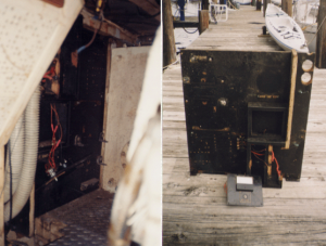
All batteries were directly connected to the power panel in the pilot house. No fusing or circuit breakers where installed and there was no common bus bars to tie into for either 12 or 24 VDC or system ground. Indeed, the distribution panel pictured above had been gutted!!! (WHY ?) So the first task was to remove the old distribution panel and clean it up. As you can see, it made quit a difference. Holes had to be epoxied, broken wood replaced and miscellaneous hardware removed. A good cleaning and repainting followed.
Partially Rebuilt Power Panel (front)
Here’s some humor in this story. After spending two weekends removing and rebuilding the panel – when I went to re-install it, I couldn’t get it to fit into through the crawl space. I took over two hours of me on my back lifting, twisting, and cursing before she finally slid into place. Thank goodness Steph wasn’t there to here me and see me afterwards! The photos above show the panel back in place. Within the next three weeks I will start wiring the panel into the trawler. The improvement in wiring runs will be tremendous.
A quick run down of what’s on the new power distribution panel from top to bottom:
- Two blank rows on the left for future installation of circuit breakers.
- The PathMaker Battery Combiner which will allow the new 12 VDC alternator to charge both house banks simultaneously.
- On the upper right a bank of fused power terminals where voltage sense and meter power for the monitors are split off.
- Bank 1 and bank 2 12 VDC fuses and terminal bus bar.
- An analog volt meter which can read power from any of the three battery banks. I may even rig it to read power from the genset.
- A two-bank 12 VDC shunt and single bank 24 VDC shunt to drive power consumption for display on the remote meters.
- The power cut off switch for the starting bank which is then routed to the 24 VDC terminal bus bar.
- The system ground bus bar.
New panel
The photo to the left shows the remote monitoring meters and display panels. At top is the Link 10 for the 24 VDC starting bank, the middle is the Link 20 to monitor the two 12 VDC house banks, and at the bottom is the status panel for the 12 VDC charger.
Even when this project is completed in February I still have not found a solution to replace the alternators on the Gardner engines. Anyone have an idea? They are direct drive units using flexible shaft couplings

[…] Wiring Project: Battery Nightmare or Dream Come True? […]